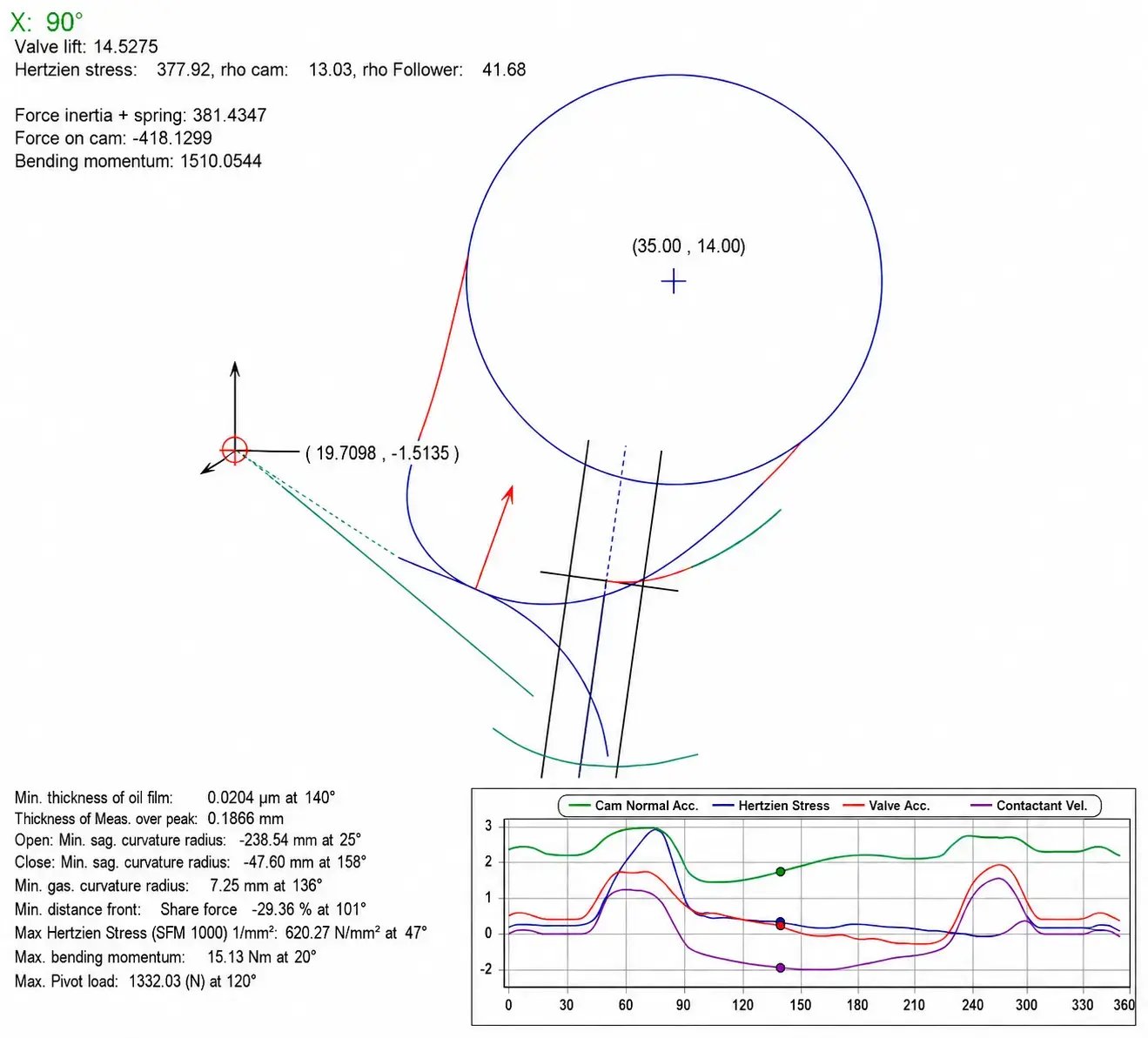
The design of a valve train starts with the required valve motion. Based on valve lift, opening duration and the geometry of the valve train, CDS calculates the corresponding cam profile.
The resulting design can be evaluated with respect to the key mechanical parameters, including:
Different valve train concepts – from direct acting systems to finger followers, rocker arms or desmodromic mechanisms – can be treated within the same design approach.
B(φ) = S″(φ)
Velocity and valve lift are obtained by integration. By modifying the spline control points and boundary conditions, engineers can systematically influence:
The spline representation produces smooth and mathematically consistent motion curves. This helps to avoid artificial high-frequency excitation and provides a reliable basis for cam profile generation and dynamic contact simulation.
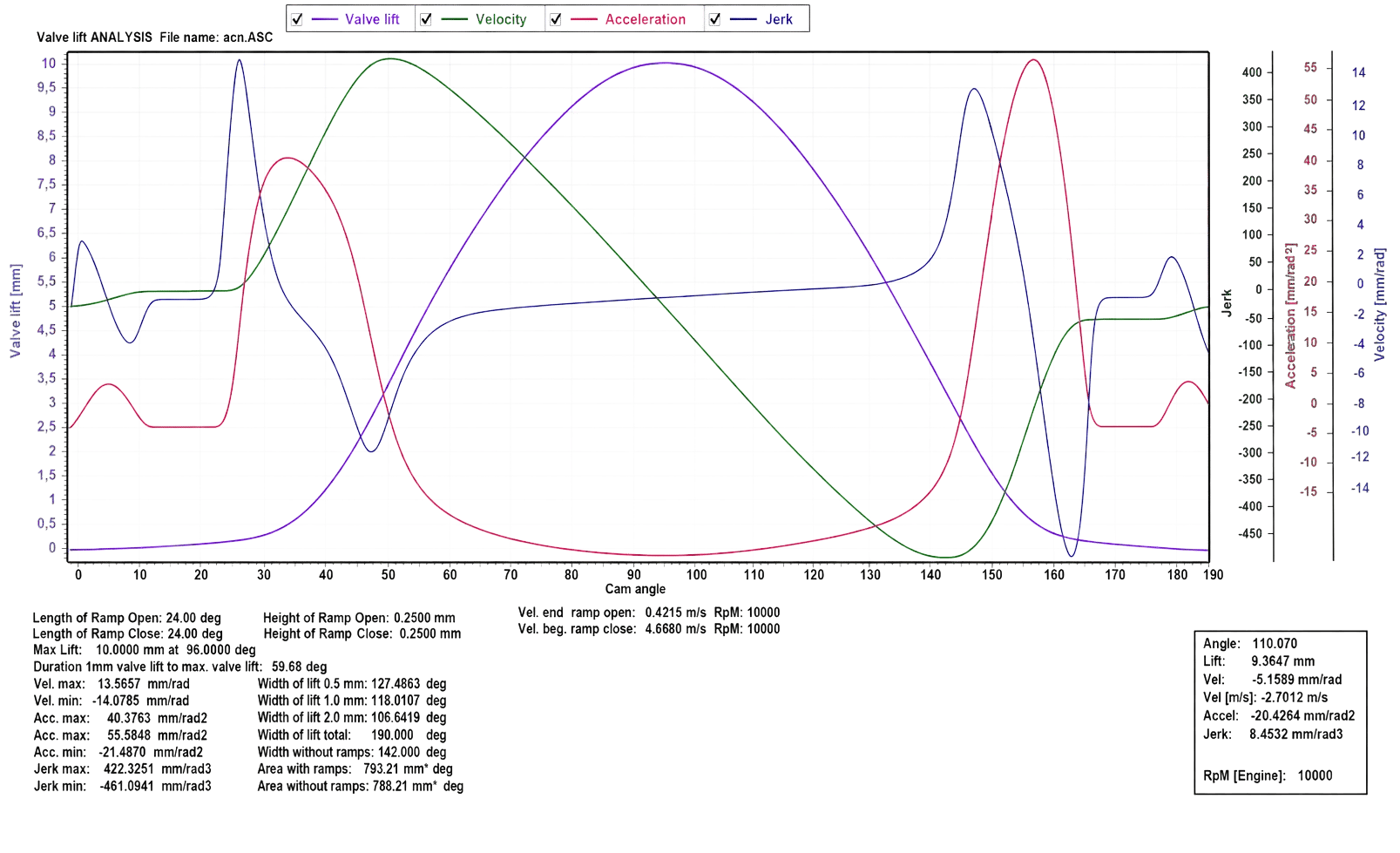
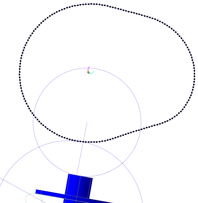
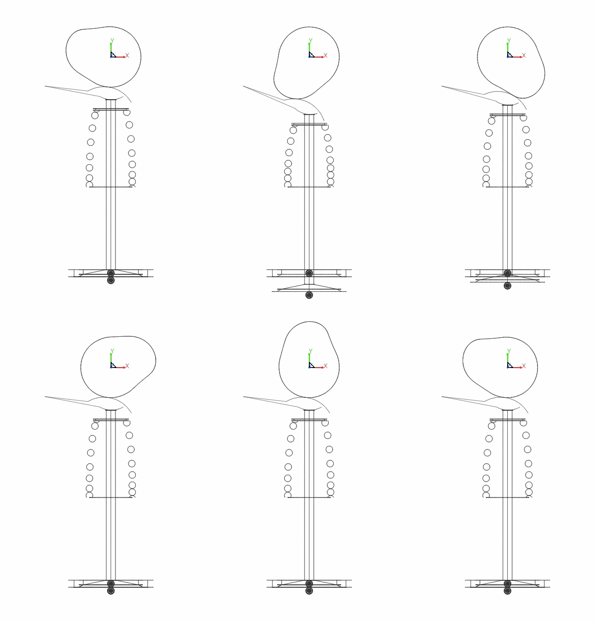
The interaction between cam and follower is at the core of the valve train dynamics. While the kinematic design defines the nominal valve motion, the actual motion depends on inertia forces, spring forces and the nonlinear contact between the individual components.
RecurDyn directly simulates these interactions in the complete mechanical system. This makes it possible to analyze:
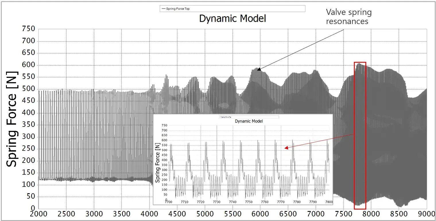
A purely kinematic force balance can provide a first estimate of the critical engine speed, but it cannot capture the dynamic interaction of the complete system. In the CDS example, the kinematic analysis predicted valve lift-off at approximately 9,660 rpm, while the dynamic simulation showed lift-off already at approximately 9,100 rpm.
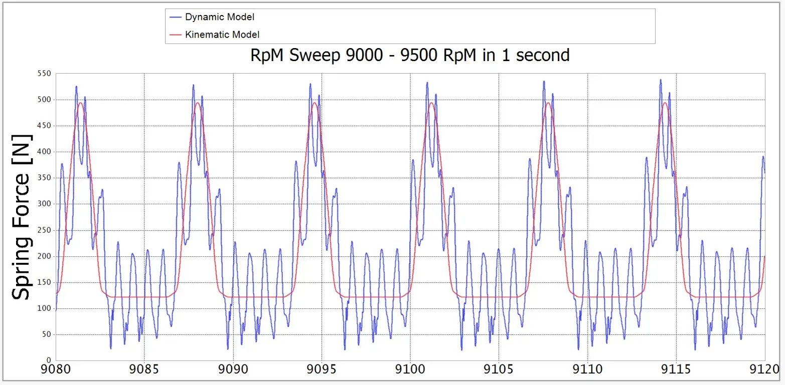
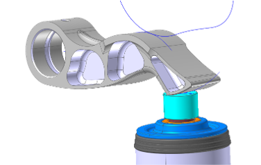
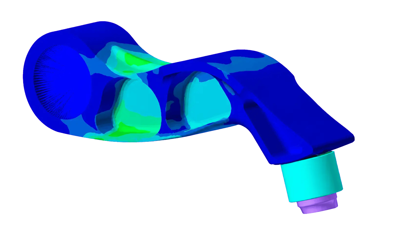
At high engine speeds, the deformation of valve train components can significantly influence the actual valve motion and the resulting contact forces. Treating components such as rocker arms, finger followers or valves as flexible bodies allows these effects to be included directly in the system dynamics.
RecurDyn combines multibody dynamics with flexible body simulation within the same model. This allows the influence of structural flexibility to be evaluated with respect to:
Flexible components can be introduced where they are relevant, while the remaining valve train stays represented by efficient rigid-body models.
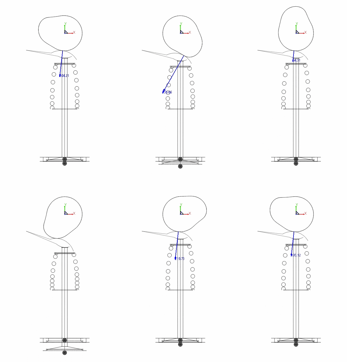
Valve springs are highly dynamic components. At increasing engine speed, their distributed mass and structural flexibility can lead to spring surge, resonances and significant deviations from the quasi-static spring force.
RecurDyn allows the valve spring to be included directly in the dynamic valve train model. Depending on the required level of detail, the spring can be represented from a simple force element up to a fully flexible FE model.
This enables the analysis of:
The spring dynamics are evaluated as part of the complete valve train rather than as an isolated component. This makes it possible to directly assess their influence on cam/follower contact and the actual valve motion.